

Shunt Resistor Original Manufacturer Selection Guide for Engineers
2026-08-28
Ask any hardware engineer about their worst current-sensing failure, and a bad shunt resistor choice often comes up. The problem isn’t finding a low milliohm value — it’s knowing which original manufacturer will actually deliver the tight tolerance, low thermal EMF, and long-term stability promised on the datasheet. That’s the question this guide tackles head-on. At Milliohm, we manufacture shunt resistors for exactly these demanding applications, and we’d rather show you what to look for than just sell you a part. Here’s the selection criteria we use when helping engineers move from prototype to production without surprises.
What the Shunt Datasheet Leaves Out
Most shunt datasheets give you a resistance tolerance and a temperature coefficient, then call it a day. What they rarely show is how the part behaves once you push short, high-current pulses through it. The element heats unevenly, the copper leads pull heat away faster than the resistive alloy, and the effective resistance can move by several times the stated TCR before the case temperature even catches up. That kind of transient error never appears in the electrical specs table.
Another gap is parasitic inductance. A four-terminal shunt may be drawn like a simple resistor, but at di/dt values common in motor drives or fast battery chargers, the small loop between the sense points can add a voltage spike that looks exactly like a current step. If you only pick the shunt by resistance and power rating, you may end up chasing noise that isn't really in your current path.
There is also the long-term drift story. Datasheets often omit how the resistance shifts after thermal cycling, vibration, or thousands of hours at elevated temperature. Solder joint aging and board flex can introduce more error than the factory tolerance, especially with low-ohmic values where milliohms of connection resistance matter.
Alloy Decisions Hiding Behind a Resistance Number
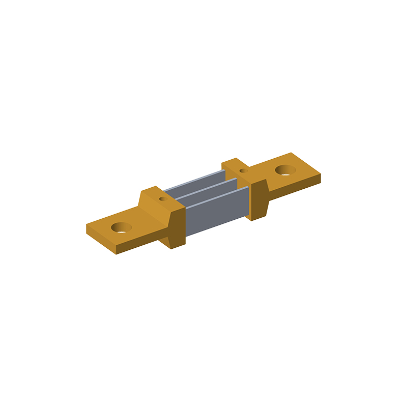
A single resistance figure on a datasheet rarely tells the full story. Behind that ohmic value sit deliberate alloy decisions: the ratio of nickel to chromium, a touch of aluminum for oxidation resistance, or a shift in manganese to stabilize the temperature coefficient. These choices are not arbitrary; they balance raw resistivity against workability, corrosion behavior, and long-term drift in the field.
For engineers, interpreting a resistance number means asking what the alloy gave up to hit that target. A lower resistivity often signals better ductility and easier drawing into fine wire, while a higher value may point to a brittle, oxidation-resistant film that handles high temperatures but cracks under repeated bending. The number is a summary of compromises rather than a starting point.
In practice, the same nominal resistance can be achieved with structurally different alloys. One might excel in thermal stability but wear out tooling faster; another could offer tighter tolerance yet sag under sustained load. Recognizing these hidden alloy trade-offs is what separates a spec-sheet match from a design that actually survives its operating environment.
Thermal Drift at the Operating Point That Actually Matters
A spec sheet drift figure is usually captured at a fixed common-mode voltage, negligible output load, and a tightly controlled ambient. Put that same part into a real front end, say an ADC driver biased at mid-scale and swinging close to the rails, and the die heats unevenly. The result isn't a uniform shift; it's a localized thermal gradient that twists offset, bias current, and even loop gain at the exact point where your signal spends most of its time.
Rather than relying on the headline ppm/°C number, sweep the input and output conditions you actually use while watching the die temperature. A low-cost method is to run a slow ramp and log drift as a function of output voltage with a small thermocouple taped to the package or an IR spot reading on the die. You'll often find the worst drift doesn't sit at room temperature or at the datasheet's test point; it lives at a rail or a bias corner. Once that point is identified, a tiny layout change, a different bias current, or a deliberately chosen part with a flatter drift surface in that region can remove more error than any calibration table.
Kelvin Layout Errors That Outweigh Resistor Tolerance
It's tempting to blame the resistor when a four-wire measurement drifts, but the real culprit is often the Kelvin sense connection itself. A sense trace that lands on the wrong side of a pad, or one that shares even a few millimeters of copper with the load current path, will capture a voltage drop that no resistor tolerance can fix.
Asymmetric routing is especially insidious. If the two sense lines don't have identical lengths and identical exposure to thermal gradients, you get a differential offset that masquerades as resistance drift. Solder joints and plated vias also introduce thermocouple junctions—tin-lead on copper alone can generate tens of microvolts per degree Celsius, which swamps the error budget of a 0.05% resistor in minutes.
The only safe approach is to bring both sense traces directly from the resistor's terminal pads, keep them parallel and tightly coupled, and avoid any via or plane transition in the sense path. Compared with these layout corrections, upgrading the resistor tolerance is almost meaningless.
How to Tell a Real Shunt Factory from a Repackager
Plenty of suppliers call themselves shunt manufacturers, but only a handful actually cut, weld, and calibrate shunts in-house. A repackager typically buys standard shunts from trading companies or second-tier plants, puts them in branded boxes, and resells at a markup. The fastest way to separate the two is to request a live video or dated photos of the production floor. Look for raw alloy strip, resistance welding stations, current cycling calibration racks, and in-house plating lines. If you only receive glossy brochure images or the same stock photos found on multiple websites, you are almost certainly dealing with a repackager.
Then test the technical conversation. A genuine shunt factory can discuss specific alloys such as manganin or CuMnNi, explain why one temperature coefficient curve fits a given application, and provide batch-level data for resistance drift, thermal EMF, and load-life cycling. They should be able to send raw measurement logs without hesitation. A repackager, by contrast, often relays your questions to an unknown third party and comes back days later with vague assurances or a datasheet copied from the original maker. Ask something concrete: 'What is the measured drift after 1,000 hours at 80°C for this shunt?' If the answer is a sales slogan rather than numbers, move on.
Finally, look at how they handle customization and compliance. Real factories can trim resistance, change terminal spacing, adjust tin or nickel plating thickness, and even switch the shunt alloy for a modest setup fee because they control tooling and raw material. They also issue certificates of conformance tied to an internal batch number and can trace every reel of alloy back to its mill certificate. Repackagers usually try to steer you toward whatever they have in stock, and their 'custom' requests get forwarded to an overseas broker with long delays. Requesting a small sample with a non-standard dimension is a quick practical test; a genuine manufacturer will produce it in days, while a repackager will stall or send something already in a warehouse.
Custom Shunt Conversations to Have Before the Schematic Freezes
The moment a schematic gets locked, every late-stage tweak becomes a costly apology. For custom shunt designs, the most painful regrets come from assumptions nobody voiced. Don't wait until layout is underway to ask how the shunt will actually be used at the board edge, what pulse profiles it must survive, or whether the sense leads need to route through a connector that doesn't exist yet. A fifteen-minute whiteboard chat about thermal drift under asymmetric load can save a respin that eats two quarters and three vendor relationships.
Engineers often freeze the shunt symbol and footprint early, then realize the alloy choice fights the ambient temperature swings near a power stage. Before the schematic review sign-off, force a conversation about the worst-case current waveform, not just the nominal rating. Ask the mechanical team if the shunt will sit near a fan intake or a sealed enclosure; ask firmware how often they sample the voltage and whether they can tolerate phase lag from a resistive element with higher inductance. These questions feel uncomfortable in the first pass and impossible in the third.
Finally, challenge the default tolerance stack before it hardens into a netlist. A 1% shunt paired with a 0.5% gain resistor and a noisy ground plane may pass a single-point simulation and fail every field unit. Discuss derating for PCB copper pours, Kelvin connection placement, and whether the shunt body needs a mechanical relief slot. When the schematic freezes without these conversations, the only custom part left is the apology.
FAQ
Ask for pulsed power derating curves, temperature coefficient of resistance across your full operating range, and short-time overload data. Reputable makers will also provide thermal impedance plots from actual measurements rather than simulations.
Look for details about alloy composition in datasheets or request a material certificate. Direct alloy control typically shows up as tighter batch-to-batch resistance spread and more predictable weld or bond line performance under thermal cycling.
Because the weld interface introduces a parasitic resistance and local heating. A poor weld can create hot spots that shift the apparent resistance under load and reduce long-term stability far more than the initial tolerance would suggest.
Beyond AEC-Q200, look for IATF 16949 process certification, full PPAP level 3 support, and evidence of in-house reliability testing like thermal shock and damp heat with continuous resistance monitoring.
Request measurement conditions: temperature gradient, lead material, and test current polarity. If a maker cannot provide a clear thermal EMF test setup, treat that as a red flag for precision current measurement applications.
Usually yes for low-ohmic values. A true Kelvin layout separates current path from voltage sense points, reducing lead and contact resistance errors. Ask for the exact geometry: some parts labeled Kelvin still share part of the current path.
Look for load life data at rated power and elevated ambient, typically 1,000 to 2,000 hours, with resistance readings at multiple intervals. Expect drift well below 0.5% for foil or manganin-based parts; makers with proprietary alloys often provide 0.1% or tighter.
Conclusion
Many engineers pick shunt resistors by resistance value and tolerance, but the datasheet hides what actually matters in a current-sensing design. The alloy behind a resistance number sets the real temperature coefficient and long-term stability, and that coefficient shifts with the operating point—not just the room-temperature spec. A shunt that looks precise on paper may drift badly at the elevated temperature where the circuit actually runs, especially if the copper traces create uneven heat flow or if the Kelvin connection isn't placed directly on the resistor's sense pads. Layout mistakes here can easily swamp the resistor's own tolerance, turning a 0.1% part into a measurement with several percent error.
Selecting an original manufacturer rather than a repackager changes the entire conversation. A real shunt factory can discuss alloy composition, trimming method, and the exact geometry that influences self-heating and inductance, while a repackager mostly moves parts and papers. Before the schematic freezes, engineers should ask about custom resistance values, non-standard dimensions, lead-free termination options, and what happens at the specific current and temperature profile the design will see. These details rarely appear in a product brief, but they determine whether the shunt survives thermal cycling, stays within calibration, and actually matches the simulation. Good supplier partnerships show up in those pre-design conversations, not in a catalog line item.
Contact Us
Contact Person: Yuying Gao
Email: [email protected]
Tel/WhatsApp: +86 18926013721
Website: https://en.milliohm.net/